

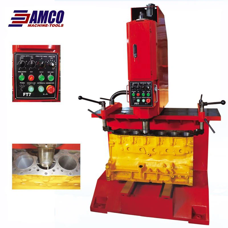
Vertical Digital Boring Machine
Description
Vertical Digital Honing Machine FT7 is mainly used for boring engine’s cylinder of automobile and tractor to retreat it. It is also applicable for boring cylinder of V engine, and other mechanical part’s holes such as cylinder sleeve of single cylinder, if some suitable fixtures are equipped.
Instruction for structure
Main components of this machine are as follows:
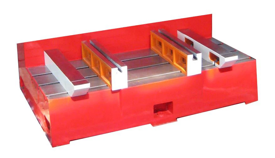
1) Work table
2) Boring component
3) Mechanism for holding cylinder
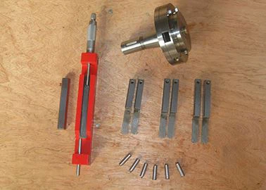
4) Special micrometer
5) Pad
6) Pneumatic control
7) Electric control
1.The upper part and lower part of the workbench as shown in the upper part is for air-bearing the boring component, in order to form air-pad for longitudinal and lateral movement; the lower part is used as a base level, on which the pending part is placed.
2.The boring component (Changeable-speed cutting mechanism) : It is a core section in the machine, which is constituted of boring bar, main axle, ballscrew, main variable-frequency motor, servo motor, centering device, main transmission mechanism, feed system and air-bearing holding device.
2.1 The boring bar : It can be moved up and down in the boring component to realize feeding of the part, and up and down moving of the part manually; and on its lower end, changeable main axle f80, main axle f52, main axle f38 (special accessory) or main axle f120 (special accessory) is installed; on lower end of the main axle, a set of numbered four racks is installed, position of each rack in square hole of the main axle rack is not arbitrarily placed but aligned, that is, the number on the rack is aligned to the number around the square hole (on outer circle) on the main axle rack for preciously positioning .
2.2 The feed system is constituted of ballscrew, servo motor and electronic handwheel (as shown in Drawing 1), thus via turning the electronic handwheel to realize up and down movement of the boring bar (each turning for 0.5mm, each scale for 0.005mm, 0.005×100=0.5mm), or via selecting function knob to position 2 and manually clicking for up and down movement to realize up and down movement of the boring bar.
2.3 The main variable-frequency motor drives the main axle of the boring bar via synchronous toothed belt (950-5M-25) to realize boring.
2.4 The centering device: Brushless DC motor is installed above the main transmission box (as shown in Drawing 1), which drives the positioning rack at lower end of the main axle via the synchronous toothed belt (420-5M-9) to realize automatic positioning.
2.5 The air-bearing holding device: A set of air-bearing, holding cylinder, upper and lower holding plates is installed at bottom of the boring component to realize positioning; when moving, the boring component is air-bored above upper surface of the work table, and after finishing positioning and when boring, the boring component is locked and held.

3.The holding mechanism : Two quick holding mechanisms with eccentric cam are respectively installed at right side and left side of the upper work table, and when the pending part is placed at lower table surface of the work table, it can be simultaneously and uniformly held down.
4.The special micrometer: This machine is equipped with measuring tool specially for measuring boring cutter, in a range of f50~f100, f80~f160, f120~f180 (special accessory) and f35~f85 (special accessory).
5.The pads: The machine is equipped with three kinds of pads offered for user to select according to different height or shape of the pending part, they are respectively: Right and left pads (same height paired) 610×70×60, pads (same height paired) 550×100×70, double pads (Special accessory).
6.Accessory holding device (as shown in Drawing 1): Two accessory holding bolts are equipped at two sides of the boring component, in case of packing, delivering and special situation, they fix the boring component; or in case of critical operation condition (holding under large cutting volume), or necessary to process under interrupted air supply or low air pressure, air-electric converter within air source controller (see Drawing 3) can be turned off, and then holding and locking, cutting.
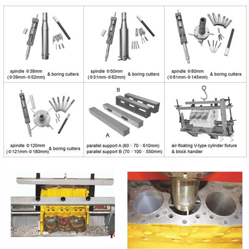
Standard accessories: Spindle Φ 50,Spindle Φ 80 ,Parallel support A ,Parallel support B, Boring cutters.
Optional accessories:Spindle Φ 38,Spindle Φ 120,Air-floating V-type cylinder fixture,Block handler.
Main Specifications
| Model | FT7 |
| Boring Diameter | 39-180mm |
| Max. Boring Depth | 380mm |
| Spindle Speed | 50-1000rpm, stepless |
| Feeding Speed of Spindle | 15-60mm/min, stepless |
| Spindle Rapid Rising | 100-960mm/min, stepless |
| Main Motor | Power 1.1kw |
| 4-step basic frequency 50Hz | |
| Synchronous speed 1500r/min | |
| Feed Motor | 0.4kw |
| Positioning Motor | 0.15kw |
| Working Pressure | 0.6≤P≤1 Mpa |
| Centering Range of Centering Rack | 39-54mm |
| 53-82mm | |
| 81-155mm | |
| 130-200mm | |
| Spindle 38mm | 39-53mm (optional) |
| Spindle 52mm | 53-82mm( standard accessory) |
| Spindle 80mm | 81-155mm(standard accessory) |
| Spindle 120mm | 121-180mm( optional) |
| Overall Dimension | 1400x930x2095mm |
| Machine Weight | 1350kg |


